X-keys XK-12 Jog & Shuttle Data Report
General Information
|
VID
|
05f3h
|
|---|---|
|
PID #1 (Factory Default)
|
0426h or 1062
|
|
PID #2
|
0428h or 1064
|
|
Consumer Usage Page
|
1
|
|
Usage Page
|
000Ch or 12
|
X-keys XK-12 Jog & Shuttle Input Report
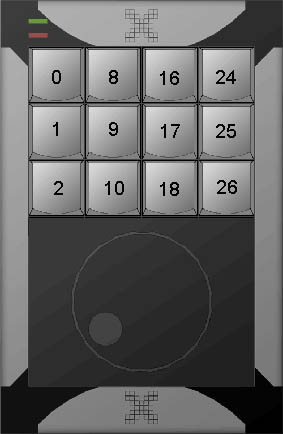
Figure 1: X-keys XK-12 Jog & Shuttle key reference.
Endpoint: 3, Consumer Usage Page.
PID #1 Additional Endpoints: 1, Keyboard (Hid Usage Page 1, Hid Usage 6)
and 2, Mouse (Hid Usage Page 1, Hid Usage 2).
PID #2 Additional Endpoints: 1, Keyboard (Hid Usage Page 1, Hid Usage 6)
and 2, Joystick (Hid Usage Page 1, Hid Usage 4).
Report Length: 33 bytes
1. General Incoming Data
This data is returned when new data is detected such as button presses, unit id change or change of the jog or shuttle. This report can be manually stimulated by sending a Generate Data output report which is very useful for obtaining the initial state of the device immediately after enumeration.
|
Byte 1*
|
Byte 2
|
Byte 3
|
Byte 4
|
Byte 5
|
Byte 6
|
Byte 7
|
Byte 8
|
Byte 9
|
Bytes 10-13
|
Bytes 14-33
|
| Constant | Unit ID | Data Type | Keys | Keys | Keys | Keys | Jog Knob | Shuttle | Time Stamp | Reserved |
|
0
|
<data>
|
PS
|
D1
|
D2
|
D3
|
D4
|
Jog
|
Shuttle
|
Time
|
value
|
PS: 0 if program switch unset, 1 if program switch is set, 2 if
generated by the Generate Data (output report 6) and program switch is unset,
3 if generated by the Generate Data (output report 6) and program switch
is set.
D1: For all bits 0 for key up, 1 for key down. Bit
1=Key 0, bit 2=Key 1, bit 3=Key 2, bit 4=Shuttle +1, bit 5=Shuttle +5, bit
6=Shuttle -1, bit 7=Shuttle -5, bit 8=Jog clockwise.
D2: For all bits 0 for key up, 1 for key down. Bit
1=Key 8, bit 2=Key 9, bit 3=Key 10, bit 4=Shuttle +2, bit 5=Shuttle +6,
bit 6=Shuttle -2, bit 7=Shuttle -6, bit 8=Jog counter clockwise.
D3: For all bits 0 for key up, 1 for key down. Bit
1=Key 16, Bit 2=Key 17, bit 3=Key 18, bit 4=Shuttle +3, bit 5=Shuttle=+7,
bit 6=Shuttle -3, bit 7=Shuttle -7, bit 8=Shuttle at rest.
D4: For all bits 0 for key up, 1 for key down. Bit
1=Key 24, Bit 2=Key 25, bit 3=Key 26, bit 4=Shuttle +4, bit 5=0, bit 6=Shuttle
-4, bit 7=0, bit 8=0.
Jog: Gives 1 for clockwise motion and 255 for counterclockwise motion.
Shuttle: Gives 1-7 for clockwise motion and 255-249 for counterclockwise
and 0 at rest.
Time: If enabled using Enable Time Stamp output report gives a time
in ms starting from when the device was plugged into a port in 4 bytes where
byte 11 is the MSB or high byte and byte 14 is the LSB or low byte.
Jog & Shuttle Note: Starting with firmware version 10 and above the Jog & Shuttle data can be read using two different ways. The first way is just reading the values of the Jog byte and the Shuttle byte, bytes 8 and 9. The second way is by reading the bytes D1-D4 and checking the bits set, the upper bits are set and unset by the Jog & Shuttle.
2. Descriptor Data
This data is returned after a Request for Descriptor output report is sent.
|
Byte 1*
|
Byte 2
|
Byte 3
|
Byte 4
|
Byte 5
|
Byte 6
|
Byte 7
|
Byte 8
|
Byte 9
|
Byte 10
|
Byte 11
|
Byte 12
|
Byte 13
|
Byte 14
|
Bytes 15-33
|
| Constant | Unit ID | Data Type | Mode | Key mapstart | Layer2 Offset | Write Report Length-1 | Read Report Length-1 | Max Columns | Max Rows | LED State | Version | PID Low | PID Hi | Reserved |
|
0
|
<data>
|
214
|
Mode
|
32
|
128
|
35
|
32
|
4
|
6
|
LEDs
|
<data>
|
PIDL
|
PIDH
|
value
|
Mode: 0 means device is in PID #1, 2 means the device is in PID
#2.
LEDs: Bit 7=1 for Green LED on, 0 for Green LED off, bit 8=1 for
Red LED on, bit 8=0 for Red LED off.
PIDL: LSB of the Product Identification number or PID.
PIDH: MSB of the Product Identification number or PID.
X-keys XK-12 Jog & Shuttle Output Report
The following types of output reports are shown in the summary below. Please be aware that several of these commands result in writing to the device's eeprom which has a limit to the number of writes allowed before it is "burnt out". The manufacturer's specification is 50,000 eeprom writes. Because of this we recommend the commands designated with e be executed rarely and not within timing loops. Note, the first byte listed in this documentation is 0 and represents the report ID. This is not present on some non-PC operating systems. So when sending an output report on Android for example, eliminate this byte.
|
Report
|
Format
|
Description
|
|---|---|---|
|
1
|
0, 186, LEDs, 0... | Set LEDs |
|
2
|
0, 179, LEDIndex, State, 0... | Index Based Set LED (Flash) |
|
3
|
0, 189, UnitID, 0... | Set Unit IDe |
|
4
|
0, 214, 0... | Request Descriptor |
|
5
|
0, 210, Enable, 0... | Enable Time Stamp |
|
6
|
0, 177, 0... | Generate Data |
|
7
|
0, 187, Bank 1 Intensity, Bank 2 Intensity, 0... | Set Backlight Intensity |
|
8
|
0, 184, 0... | Toggle Backlights |
|
9
|
0, 183, ScrLk, 0... | Enable Scroll Lock to Toggle Backlights |
|
10
|
0, 182, Bank, OnOff, 0... | Turn On/Off Rows of Backlights |
|
11
|
0, 181, Index, State, 0... | Index Based Set Backlights (Flash) |
|
12
|
0, 180, Freq, 0... | Set Frequency of Flash |
|
13
|
0, 199, Save, 0... | Save Backlight State to EEPROMe |
|
14
|
0, 204, Mode, 0... | Change PIDe |
|
15
|
0, 201, Modifier, 0, HC1, HC2, HC3, HC4, HC5, HC6, 0... | Keyboard Reflector |
|
16
|
0, 203, Buttons, Mouse X, Mouse Y, Wheel X, Wheel Y, 0... | Mouse Reflector (PID #1 only) |
|
17
|
0, 202, Joystick X, Joystick Y, Joystick Z rot., Joystick Z, Joystick Slider, Game Buttons 1, Game Buttons 2, Game Buttons 3, Game Buttons 4, 0, Point of View Hat, 0... | Joystick Reflector (PID #2 only) |
eCommand writes to EEPROM, do not
perform this command excessively, do not exceed 50,000 writes to EEPROM.
Endpoint: 4, Vendor Defined Usage Page.
Report Length: 36 bytes.
1. Set LEDs
One of two methods for controlling the LEDs.
|
Byte 1*
|
Byte 2
|
Byte 3
|
Bytes 4-36
|
| Constant | Command | LED Control | Constant |
|
0
|
186
|
LEDs
|
0
|
LEDs: Bits 1-6=0, bit 7=1 to turn on Green LED or 0 to turn off Green LED, bit 8=1 to turn on Red LED or 0 to turn off Red LED.
2. Index Based Set LED (Flash)
One of two methods for controlling the LEDs. If flashing of LEDs is desired this method must be used.
|
Byte 1*
|
Byte 2
|
Byte 3
|
Byte 4
|
Bytes 5-36
|
| Constant | Command | LED Index | LED State | Constant |
|
0
|
179
|
LEDIndex
|
LEDState
|
0
|
LEDIndex: 6 = green, 7 = red.
LEDState: 0 = off, 1 = on and 2 = flash. Set the frequency of the
flash with output report 12. Set Frequency of Flash.
3. Set Unit ID
Send this output report to set the Unit ID of the device. This is useful if connecting more than one of the same device to the a computer.
|
Byte 1*
|
Byte 2
|
Byte 3
|
Bytes 4-36
|
| Constant | Command | Unit ID (0-255) | Constant |
|
0
|
189
|
value
|
0
|
4. Request Descriptor
After sending this output report a Descriptor input report will be generated.
|
Byte 1*
|
Byte 2
|
Bytes 3-36
|
| Constant | Command | Constant |
|
0
|
214
|
0
|
5. Enable Time Stamp
By default the Time Stamp feature is enabled. To turn off send this command with Byte 3=0.
|
Byte 1*
|
Byte 2
|
Byte 3
|
Bytes 4-36
|
| Constant | Command | Enable | Constant |
|
0
|
210
|
0=off, 1=on
|
0
|
6. Generate Data
After sending this output report a General Incoming Data input report will be generated with bit 2 of PS set. This is useful in determining the initial state of the device before any data has changed.
|
Byte 1*
|
Byte 2
|
Bytes 3-36
|
| Constant | Command | Constant |
|
0
|
177
|
0
|
7. Set Backlight Intensity
|
Byte 1*
|
Byte 2
|
Byte 3
|
Byte 4
|
Bytes 4-36
|
| Constant | Command | Bank 1 Intensity | Bank 2 Intensity | Constant |
|
0
|
187
|
Intensity
|
Intensity
|
0
|
Intensity: 0-255 where 0 is no intensity for that color or off,
and 255 is the brightest.
8. Toggle Backlights
|
Byte 1*
|
Byte 2
|
Bytes 3-36
|
| Constant | Command | Constant |
|
0
|
184
|
0
|
9. Enable Scroll Lock to Enable Backlights
Send this output report with ScrLk=128 to enable the standard keyboard's ScrLk key to toggle the backlights.
|
Byte 1*
|
Byte 2
|
Byte 3
|
Bytes 4-36
|
| Constant | Command | Enable/Disable | Constant |
|
0
|
183
|
ScrLk
|
0
|
ScrLk: 0 to disable Scroll Lock, 128 to enable Scroll Lock to toggle backlighting.
10. Turn On/Off Rows of Backlights
Send this output report to either turn on or off rows of the backlights.
|
Byte 1*
|
Byte 2
|
Byte 3
|
Byte 4
|
Bytes 5-36
|
| Constant | Command | Bank # | State | Constant |
|
0
|
182
|
Bank
|
OnOff
|
0
|
Bank: 0 = bank 1, 1 = bank 2.
OnOff: For all bits 0 for no backlighting, 1 for backlighting. Bit
0 = 1st row, bit 1=2nd row, bit 2=3rd row, bit 3=4th row, bit 4=5th row,
bit 5=6th row. Note the intensities are not affected by this command.
11. Index Based Set Backlights (Flash)
Another method to control the backlights. If flashing of backlights is desired this method must be used.
|
Byte 1*
|
Byte 2
|
Byte 3
|
Byte 4
|
Bytes 5-36
|
| Constant | Command | Key Index | State | Constant |
|
0
|
181
|
Index
|
State
|
0
|
Index: For bank 1 equals the index given in Figure 1. For bank 2
add 32 to the index given in Figure 1. For example to control the lower
left key bank 1 index=5, the corresponding bank 2 is index=37.
State: 0 = off, 1 = on and 2 = flash. Set the frequency of the flash
with output report 12. Set Frequency of Flash.
12. Set Frequency of Flash
Use this output report to control the frequency of the flashing of both the indicator LEDs and the backlights, same frequency is used for both.
|
Byte 1*
|
Byte 2
|
Byte 3
|
Bytes 4-36
|
| Constant | Command | Frequency | Constant |
|
0
|
180
|
Freq
|
0
|
Freq: 1-255 where 1 is the fastest flash and 255 is the slowest. 255 is approximately 4 seconds between flashes.
13. Save Backlight State to EEPROM
Send this output report to change the default backlighting on startup of device to the current backlight state, ie, what ever backlights are on or off at the time this report is sent will be the new default.
|
Byte 1*
|
Byte 2
|
Byte 3
|
Bytes 4-36
|
| Constant | Command | Save | Constant |
|
0
|
199
|
Save
|
0
|
Save: Any value other than 0 will save the current backlight state to the EEPROM so when the device is replugged it will display this save backlighting. Note because there is a limited number of times the EEProm can be written to, it is not a good idea to do this often.
14. Change PID
Send this output report to change between the two PIDs. This needs to be done only if the user wishes to have the joystick endpoint.
|
Byte 1*
|
Byte 2
|
Byte 3
|
Bytes 4-36
|
| Constant | Command | Mode | Constant |
|
0
|
204
|
Mode
|
0
|
Mode: 0 for PID #1, reporting to the USB as a Splat device (IN and OUT), a mouse, and a keyboard and 2 for PID #2, reporting as a Splat device (IN and OUT), joystick and a keyboard.
15. Keyboard Reflector
Sends native keyboard messages.
|
Byte 1*
|
Byte 2
|
Byte 3
|
Byte 4
|
Byte 5
|
Byte 6
|
Byte 7
|
Byte 8
|
Byte 9
|
Byte 10
|
Bytes 11-36
|
| Constant | Command | Modifier | Constant | Hid Code 1 | Hid Code 2 | Hid Code 3 | Hid Code 4 | Hid Code 5 | Hid Code 6 | Constant |
|
0
|
201
|
Modifier
|
0
|
HC1
|
HC2
|
HC3
|
HC4
|
HC5
|
HC6
|
0
|
Modifier: Bit 1=Left Ctrl, bit 2=Left Shift, bit 3=Left Alt, bit
4=Left Gui, bit 5=Right Ctrl, bit 6=Right Shift, bit 7=Right Alt, bit 8=Right
Gui.
HC1=Hid Code for 1st key down, or 0 to release previous key press
in this byte position.
HC2=Hid Code for 2nd key down, or 0 to release previous key press
in this byte position.
HC3=Hid Code for 3rd key down, or 0 to release previous key press
in this byte position.
HC4=Hid Code for 4th key down, or 0 to release previous key press
in this byte position.
HC5=Hid Code for 5th key down, or 0 to release previous key press
in this byte position.
HC6=Hid Code for 6th key down, or 0 to release previous key press
in this byte position.
16. Mouse Reflector
Sends native mouse messages (PID #1 only).
|
Byte 1*
|
Byte 2
|
Byte 3
|
Byte 4
|
Byte 5
|
Byte 6
|
Byte 7
|
Bytes 8-36
|
| Constant | Command | Buttons | Mouse X | Mouse Y | Wheel X | Wheel Y | Constant |
|
0
|
203
|
Buttons
|
X
|
Y
|
WX
|
WY
|
0
|
Buttons: Bit 1=Left, bit 2=Right, bit 3=Center, bit 4=XButton1,
bit 5=XButton2.
X=Mouse X motion. 0 no motion, 1-127 is right, 255-129=left,
finest inc (1 and 255) to coarsest (127 and 129).
Y=Mouse Y motion. 0 no motion, 1-127 is down, 255-129=up, finest
inc (1 and 255) to coarsest (127 and 129).
WX=Wheel X. 0 no motion, 1-127 is up, 255-129=down, finest inc
(1 and 255) to coarsest (127 and 129).
WY=Wheel Y. 0 no motion, 1-127 is up, 255-129=down, finest inc
(1 and 255) to coarsest (127 and 129).
17. Joystick Reflector
Sends native joystick messages (PID #2 only).
|
Byte 1*
|
Byte 2
|
Byte 3
|
Byte 4
|
Byte 5
|
Byte 6
|
Byte 7
|
Byte 8
|
Byte 9
|
Byte 10
|
Byte 11
|
Byte 12
|
Byte 13
|
Bytes 14-36
|
| Constant | Command | Joystick X | Joystick Y | Joystick Z rot. | Joystick Z | Joystick Slider | Game Buttons | Game Buttons | Game Buttons | Game Buttons | Constant | Point of View Hat | Constant |
|
0
|
202
|
X
|
Y
|
Z rot.
|
Z
|
Slider
|
GB1
|
GB2
|
GB3
|
GB4
|
0
|
Hat
|
0
|
X: Joystick X, 0-127 is from center to full right, 255-128 is from
center to full left.
Y: Joystick Y, 0-127 is from center to bottom, 255-128 is from center
to top.
Z rot.: Joystick Z rot., 0-127 is from center to bottom, 255-128
is from center to top.
Z.: Joystick Z, 0-127 is from center to bottom, 255-128 is from center
to top.
Slider: Joystick Slider, 0-127 is from center to bottom, 255-128
is from center to top.
GB1: Game buttons 1-8, bit 1= game button 1, bit 2=game button 2,
etc.
GB2: Game buttons 9-16, bit 1= game button 9, bit 2=game button 10,
etc.
GB3: Game buttons 17-24, bit 1= game button 17, bit 2=game button
18, etc.
GB4: Game buttons 25-32, bit 1= game button 25, bit 2=game button
26, etc.
Hat: 0 to 7 clockwise, 8 is no hat.
*This first byte may be omitted on some non-PC operating systems. On these systems the read and write lengths will be 1 byte smaller.
Back to top